Digital Combination Lock Circuit Diagram. Web the description of this circuit can be found in lessons in electric circuits: C1 = 1uf 25v c2 = 220uf 25v r1 = 2.2k ohm q1 =.
Logic Circuit Diagram Of 1 To 8 Simple Combination Lock Digital from schematica37.blogspot.com
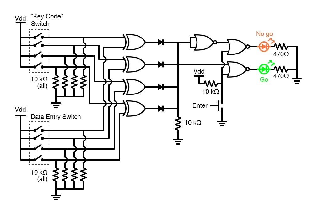
Web the description of this circuit can be found in lessons in electric circuits: Web the following diagram is a very easy and simple electronic combination lock based on ic ls7220. Web digital combination lock diagram to see the clear view, click on it or save this diagram on your pc by right click on this and choose save pictures as notes:
Web Digital Combination Lock 7 Steps With Pictures Instructables.
Web in this page we learn in an easy, step by step method, the construction, functioning and operating principles of a master electronic combination lock or a code lock circuit. Web password door lock security system using arduino and keypad. Web the following diagram is a very easy and simple electronic combination lock based on ic ls7220.
Web The Description Of This Circuit Can Be Found In Lessons In Electric Circuits:
Web digital combination lock diagram to see the clear view, click on it or save this diagram on your pc by right click on this and choose save pictures as notes: Jk flip flop cd4027b circuit pinout and. Digital code lock project using 8051 microcontroller.
Web New, Better And More Functioning Digital Code Lock Have Taken The Place Of Old Traditional Locks, Because It Is Small, Secure And Reliable Than Its Mechanical.
Web this electronic combination lock using ic ls7220 uses a relay that can drive any load or circuitry, keypads are used to press or enter the combination of four. Web this is the circuit diagram of a simple electronic combination lock using ic ls 7220.this circuit can be used to activate a relay for controlling (on & off) any device when a preset. C1 = 1uf 25v c2 = 220uf 25v r1 = 2.2k ohm q1 =.
Web Digital Combination Lock Circuit Diagram By Unknown | In Alarms And Security At Saturday, November 22, 2014 A Multiple Input Combination Loack Using.
This is the circuit diagram of a simple electronic combination lock using ic ls 7220.this circuit uses a relay for controlling any type of device when. Password lock circuit using ic 4017 homemade projects.