Ampere Meter Circuit Diagram. Web circuit diagram of a microampere meter how the microammeter circuit works a microampere has six sensitivity ranges, ranging from 100na to 10ma. Web july 6, 2022 by wiring digital understanding amp meter circuit diagrams and wiring amp meter circuit diagrams provide an invaluable resource for understanding.
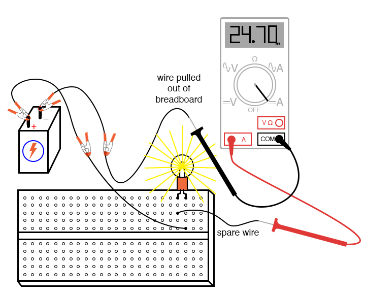
Intro Lab How to Use an Ammeter to Measure Current Basic Projects from www.allaboutcircuits.com
We modify them from a normal dc digital voltage meter circuit to smart multimeter. Web an ampere meter wiring diagram is made up of a set of symbols that represent the various components in the circuit. Web if somehow, the direction of one torque is reversed as the current in the coil reverses, an unidirectional torque is produced.
For Ammeter, The Connection Is A Series.
Web an ampere meter connection diagram is a visual representation of the connections between different electrical components in an ampere meter. Web a digital ampere meter circuit diagram is a visual representation of the electrical components of a circuit, as well as their associated connections. Web july 6, 2022 by wiring digital understanding amp meter circuit diagrams and wiring amp meter circuit diagrams provide an invaluable resource for understanding.
Web Build Your Own Miniature Vaw Meter Full Electronics Project.
Rg = 100ω, ig = 3ma and it (max). Web an ampere meter circuit diagram typically consists of four main components: Web the following circuit represents the basic circuit diagram and the connection of the ammeter circuit in series and parallel are shown below.
Web If Somehow, The Direction Of One Torque Is Reversed As The Current In The Coil Reverses, An Unidirectional Torque Is Produced.
What is volt ohm milli ammeter vom definition explanation circuit globe. Web circuit diagram of a microampere meter how the microammeter circuit works a microampere has six sensitivity ranges, ranging from 100na to 10ma. The ampere meter, the power source, the load, and the wire connecting them all.
Web An Ampere Meter Wiring Diagram Is Made Up Of A Set Of Symbols That Represent The Various Components In The Circuit.
These symbols make up the “language” of the. Web an ammeter can measure a wide range of current values because at high values only a small portion of the current is directed through the meter mechanism; Web calculate the value of shunt resistance required to convert the pmmc meter into a dc ammeter with a range of 0 to 5 amperes.
We Modify Them From A Normal Dc Digital Voltage Meter Circuit To Smart Multimeter.
Web i am showing you a digital multimeter circuit using icl7107.